
Interface & Assembly Envelope
Provide the mounting interface, available space and nearby components with the required field specification.
Review an array applicationThe Halbach geometry concentrates flux on the working face and suppresses the back field. Array geometry can increase the field in the specified working region. Review the stated gain with the comparison geometry, gap and agreed validation method., with complete assembly, positioning and magnetic verification support.
Product forms, uses and selection considerations. Final specifications are agreed for each project.
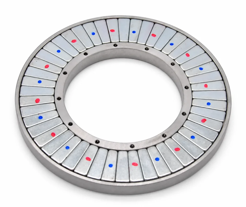
Circular arrangement with defined orientation and support.

Linear sequence for the specified working-side field.
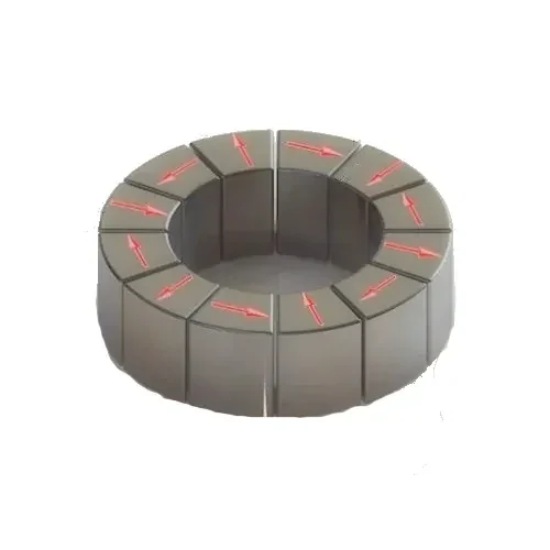
Segment geometry shapes the intended field region.
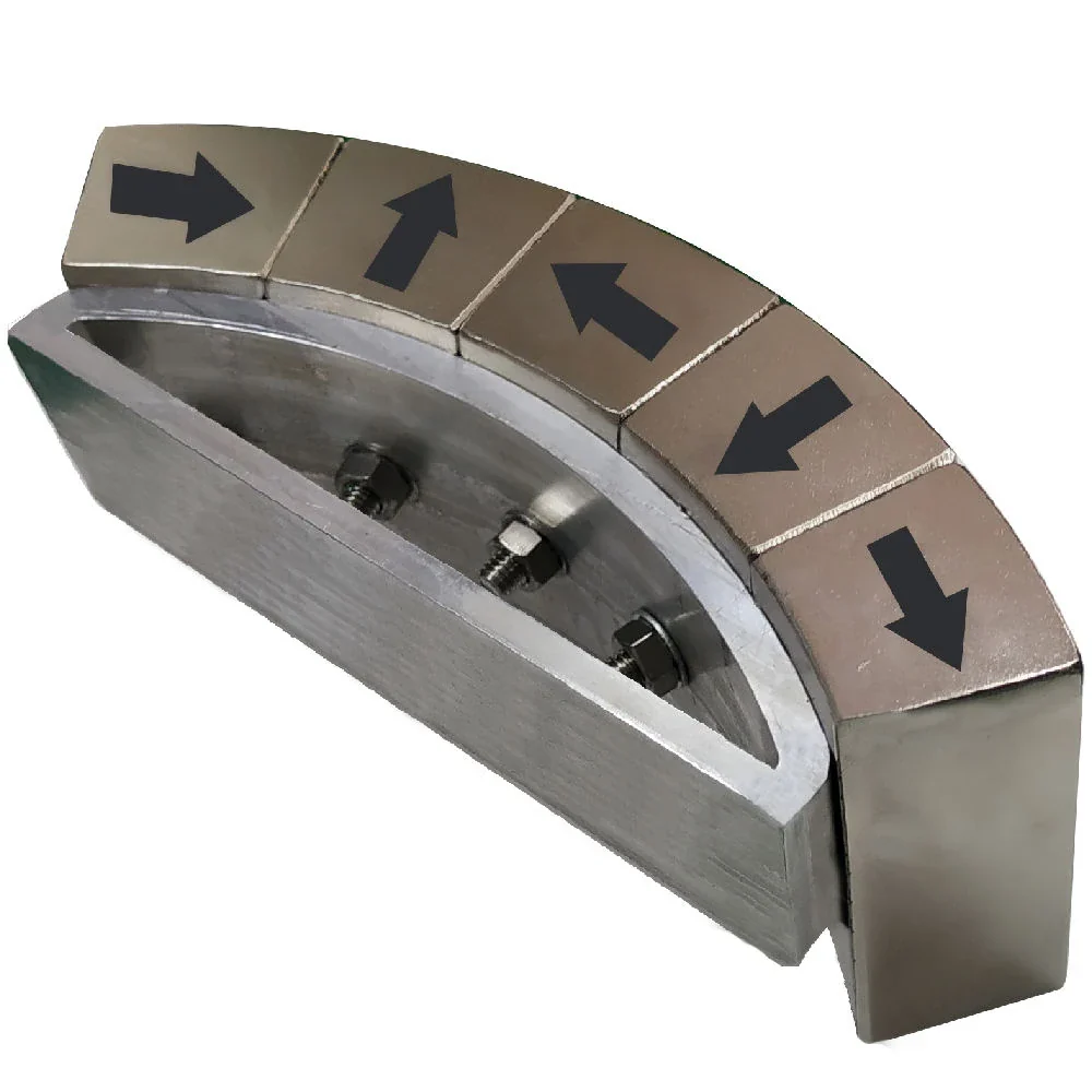
Retention and working gap reviewed with orientation.

Define a segment sequence and magnetization direction for the required working region. A circular bore and a linear working face need different field specifications.
State working distance, mapped volume and retention interfaces. Review the fixture and assembly sequence alongside the agreed field-map acceptance criteria.
Review array configurations SELECTION GUIDEApplication selection notesExplore applications and requirements
A single magnet has flux on both faces. Rotate successive magnets by 90° and the flux constructively interferes on one side while destructively canceling on the other.
| Application | Typical Spec | Why This Material |
|---|---|---|
| Brushless DC Motors | Cylindrical Halbach rotor | Back-EMF shaping; cogging also depends on the stator and complete motor design |
| Magnetic Levitation | Linear Halbach track | Strong one-sided lift force for maglev systems |
| Particle Accelerators | Hybrid Halbach (NdFeB + SmCo) | Precision field shaping for beam control |
| MRI & NMR | Cylindrical Halbach | Compact, open MRI designs without superconducting magnets |
| Magnetic Refrigeration | Rotating Halbach | Field switching for magnetocaloric cooling |
We design the array to your field spec.
| Configuration | Geometry | Field Gain | Typical Use | Notes |
|---|---|---|---|---|
| Linear Halbach | Straight row, 90° rotation | 1.4× vs flat array | Maglev tracks, separators | Simple assembly, modular |
| Cylindrical Halbach | Ring, continuous k=1 rotation | 2× vs uniform ring | Motor rotors, MRI | Highest center field |
| Dipole (2-sided) | Rectangular yoke-free | High uniformity | Accelerators, sensors | Uniform field region |
| 4-Sided Halbach | Square cross-section | Very high center field | Analytical instruments | Compact flux concentrator |
We provide complete Halbach design services:
Halbach arrays are challenging to assemble — magnetic forces can rotate or displace segments during assembly. Fixtures and retention must control the assembly sequence:
Process reference images are separated from the product gallery. They illustrate equipment and handling topics; they do not establish ownership of a facility, a customer delivery, or project-specific inspection results.
Halbach arrays depend on accurate component geometry, safe fixture-controlled assembly, pole-orientation control and mapped field performance.

Machining equipment controls arc, wedge and interface geometry.

Robotic fixtures manage orientation, placement and integrated magnetic checks.
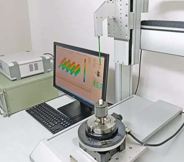
A motorized Hall-probe scanner maps field strength and distribution across the Halbach working surface.
Pole directions and segment order follow the approved assembly drawing. Transport restraints and protective packing are specified separately.
More segments create a better approximation of the ideal continuous Halbach. A 4-segment sequence is a coarse approximation; 8–16 segments is a common design starting point. Select the count using the required field region, harmonic content, working gap, assembly constraints and cost; the benefit is geometry-dependent.
No — the same forces that create the one-sided field try to rotate and eject the segments. Every Halbach needs a housing, adhesive, and/or mechanical retention. We design retention based on your vibration and shock requirements.
Yes — send your target field strength, geometry envelope, and uniformity requirements. We'll simulate your array, propose a segment design, and provide field plots for your review before cutting any material.
Segment orientation, position and gaps all influence field quality. The published ±1° angular and ±0.05mm positioning references should be tied to drawing datums and an agreed field-map acceptance plan; their relative importance depends on the geometry.
Segments bonded in precision fixtures with structural adhesive; bond lines and gap tolerances controlled to hold the calculated field profile.
Hall-probe scanning of the assembled array against FEA prediction — working-region field strength, uniformity and residual back-side field checked against the agreed acceptance limits.
Potting or banding for mechanical and environmental protection; arrays can be integrated onto shafts, back-irons or customer structures.
Provide the mounting interface, available space and nearby components with the required field specification.
Review an array applicationSend it to our team — we'll review the design and quote it as a validated, ready-to-install assembly.