
Assembly interfaces
- Shaft datumAxis, bearing seats and mechanical fit
- Housing envelopeRetention and mating geometry
- Delivery boundaryParts and acceptance records included
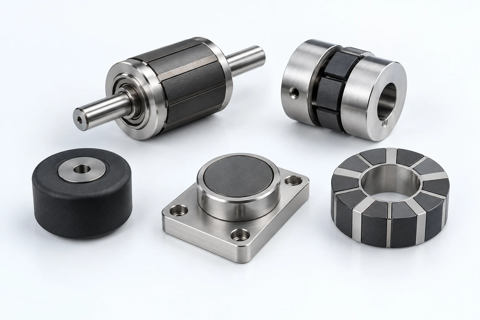
Rotors, arrays, couplings and encapsulated components supplied to an assembly drawing and acceptance plan.
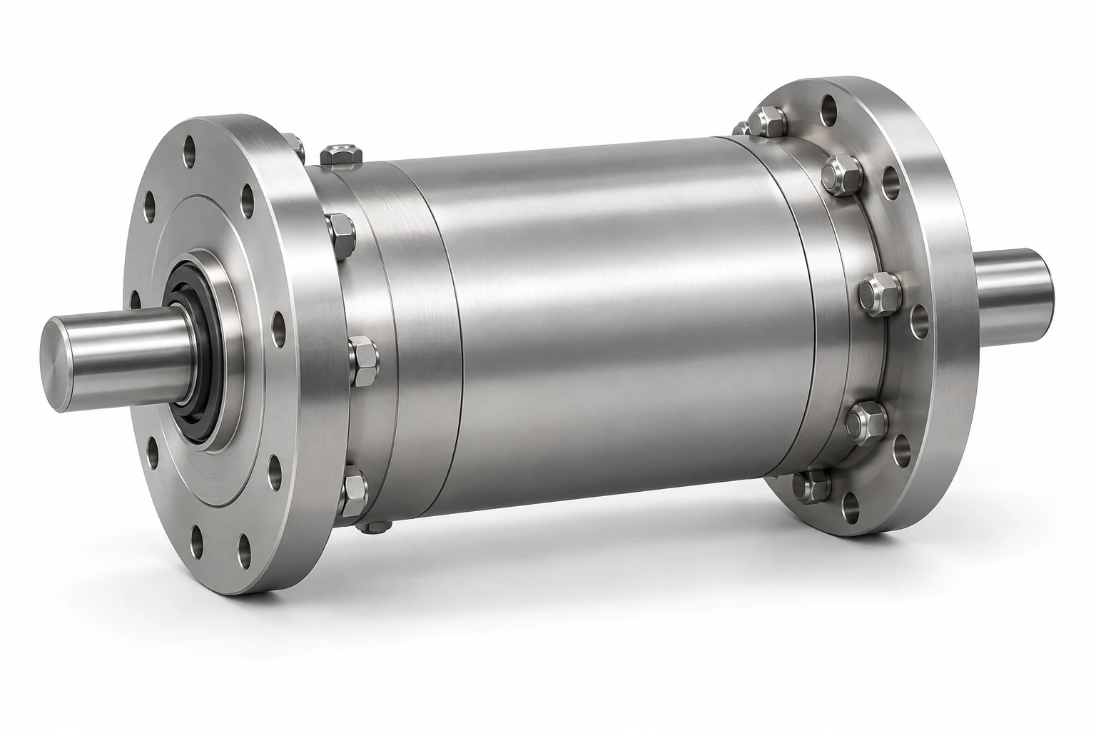
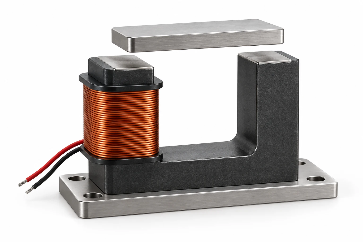
Assembly interfaces
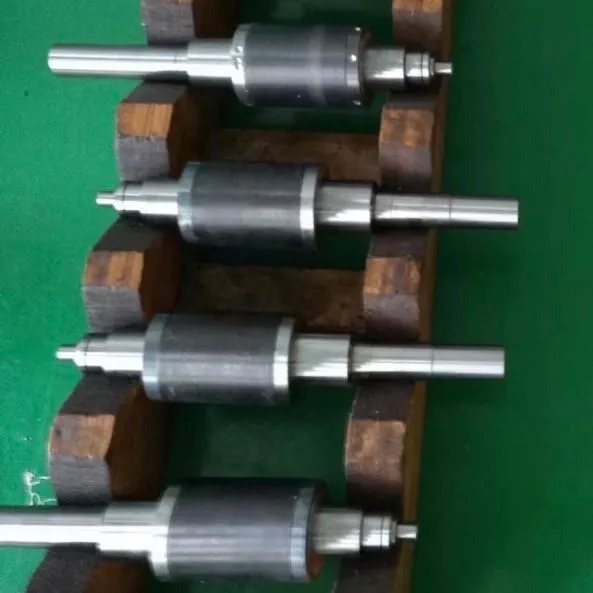
Shaft, bearing seats, rotor envelope and retention.
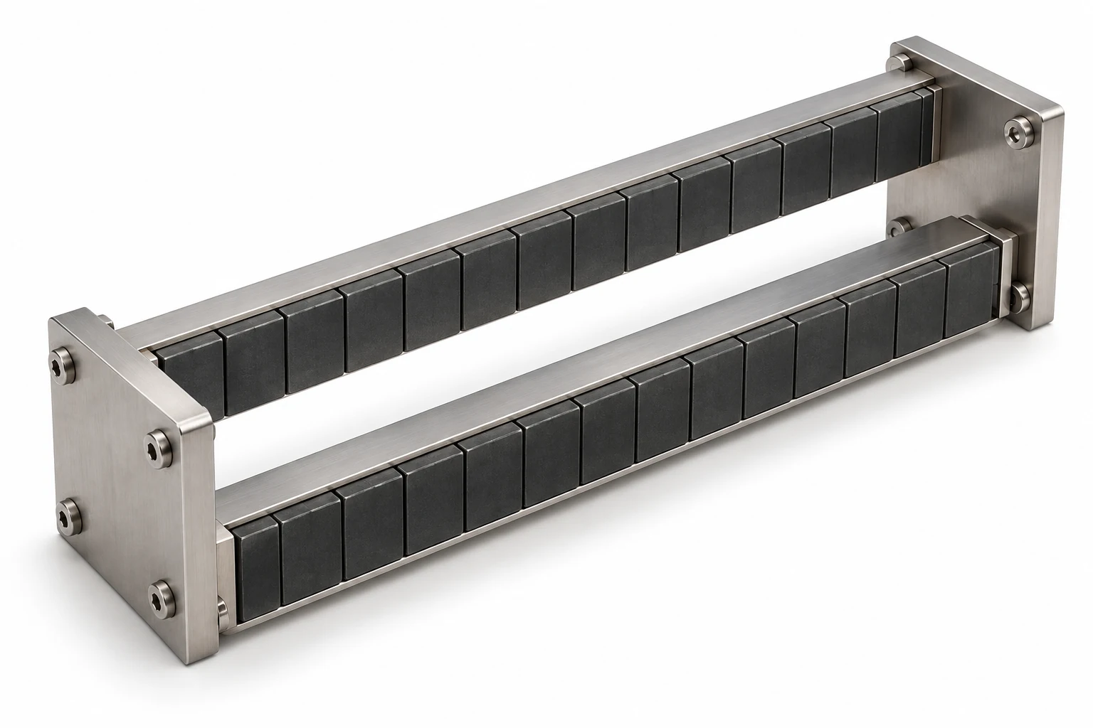
Array geometry, magnetization directions and the working region.
Driving side, driven side, containment barrier and operating gap.
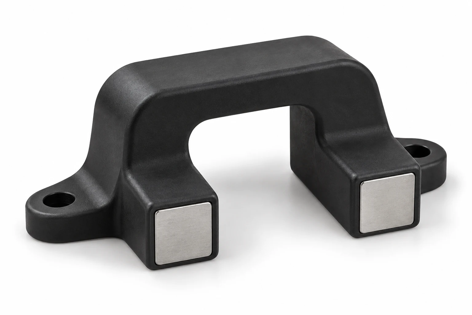
Magnet, polymer, insert geometry and exposure conditions.
Assembly drawing, BOM, interface datums and the delivery boundary.
Axial-flux rotors, linear-motor tracks and wind-generator pole assemblies extend the rotating, translating and field-shaping design options. Review air gap, pole geometry, retention, thermal behavior and the complete-part test boundary through the rotor, Halbach or custom assembly route. Confirm production responsibility and the proposed build before committing the assembly scope.
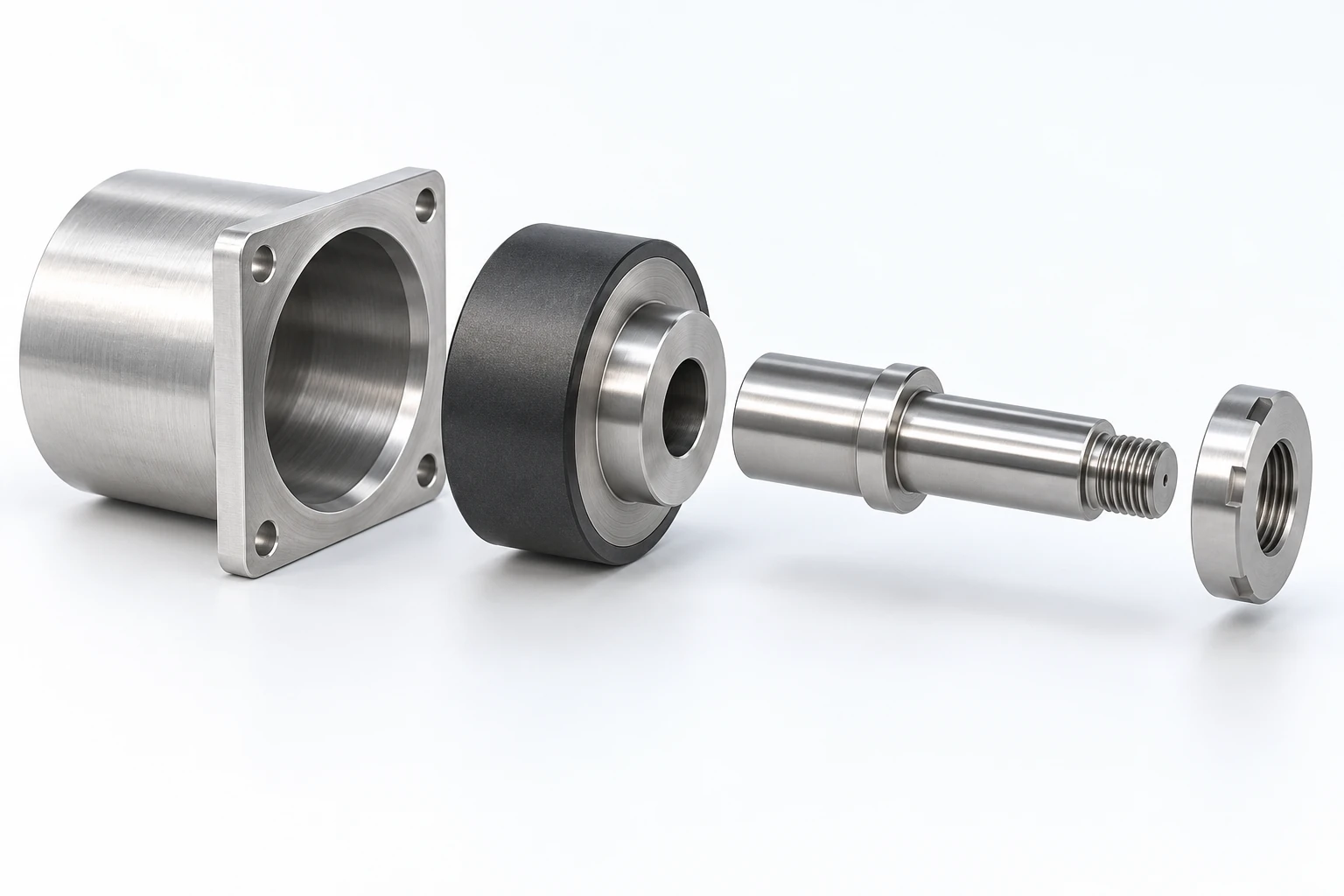
Owned production and test-line equipment.
Rotor-balancing process reference.
Magnetic-coupling production reference.
A complete assembly gives you fewer part numbers, suppliers and shipments to manage, with one agreed inspection plan.
We control the magnet grade, the steel composition, and the air gap — and verify the assembled performance, not just the components.
Assembly-level test records are supplied according to the agreed inspection plan, including torque, flux, pull force or back-EMF where applicable.
Confirm which magnets, shafts, housings, retention features and customer-supplied parts are included in the order. Interface drawings, inspection criteria, approved revisions and test records define the delivery—not the appearance of the assembly alone.
Connect each measured result to a defined assembly revision and test arrangement. This review record helps both teams distinguish a design change from a change in the way the assembly is measured.
Scroll horizontally on a small screen to read all three columns.
| Review point | Bring to the review | Record before moving on |
|---|---|---|
| Drawing baseline | Current assembly revision, material inputs and the operating conditions behind the required output. | Open assumptions, agreed design changes and which party approves each change. |
| Sample build | Sample identification, component revisions and the proposed inspection method. | Any departure from the intended production process and its effect on the sample evaluation. |
| System correlation | Fixture drawing, working gap, sensor or load position, test temperature and installation conditions. | Measured results, repeatability observations and differences between bench and application tests. |
| Production release | Approved sample results and any outstanding actions. | Released drawing revision, acceptance limits, sampling plan and the records required with delivery. |
Assembly-level detail helps us quote a finished, tested part — not just components.
Include the drawing revision, sample approval criteria and required delivery milestones with your inquiry.
Prepare your RFQProvide the assembly drawing or BOM, magnetic function, mechanical interfaces, included parts and finished-assembly acceptance plan.
Confidential RFQ · NDA available upon request.