
Release & Revision Control
Identify the approved drawing revision, sample reference and acceptance records for a repeat-order handover.
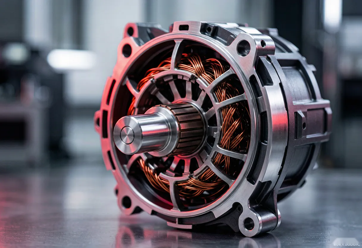
Review program qualificationEngineered magnetic assemblies for motors, pumps and specialized industrial systems — from individual magnets to validated, ready-to-install rotors. Magnets bonded or insert-molded onto shafts and lamination stacks, magnetized, dynamically balanced, and flux-verified.
Product forms, uses and selection considerations. Final specifications are agreed for each project.
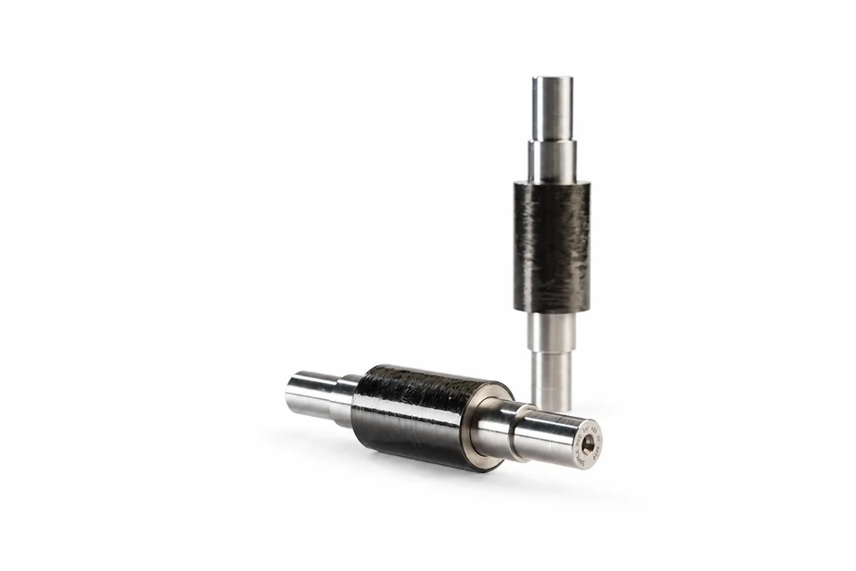
Retention reviewed for speed and mechanical loads.
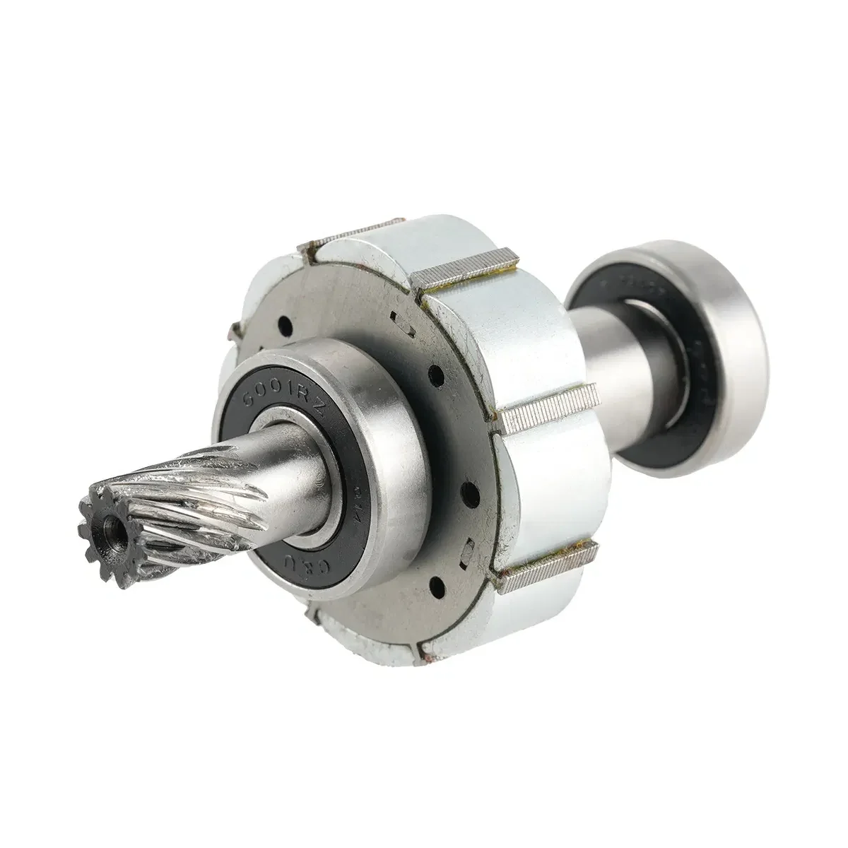
Rotor, shaft and mating interfaces defined together.
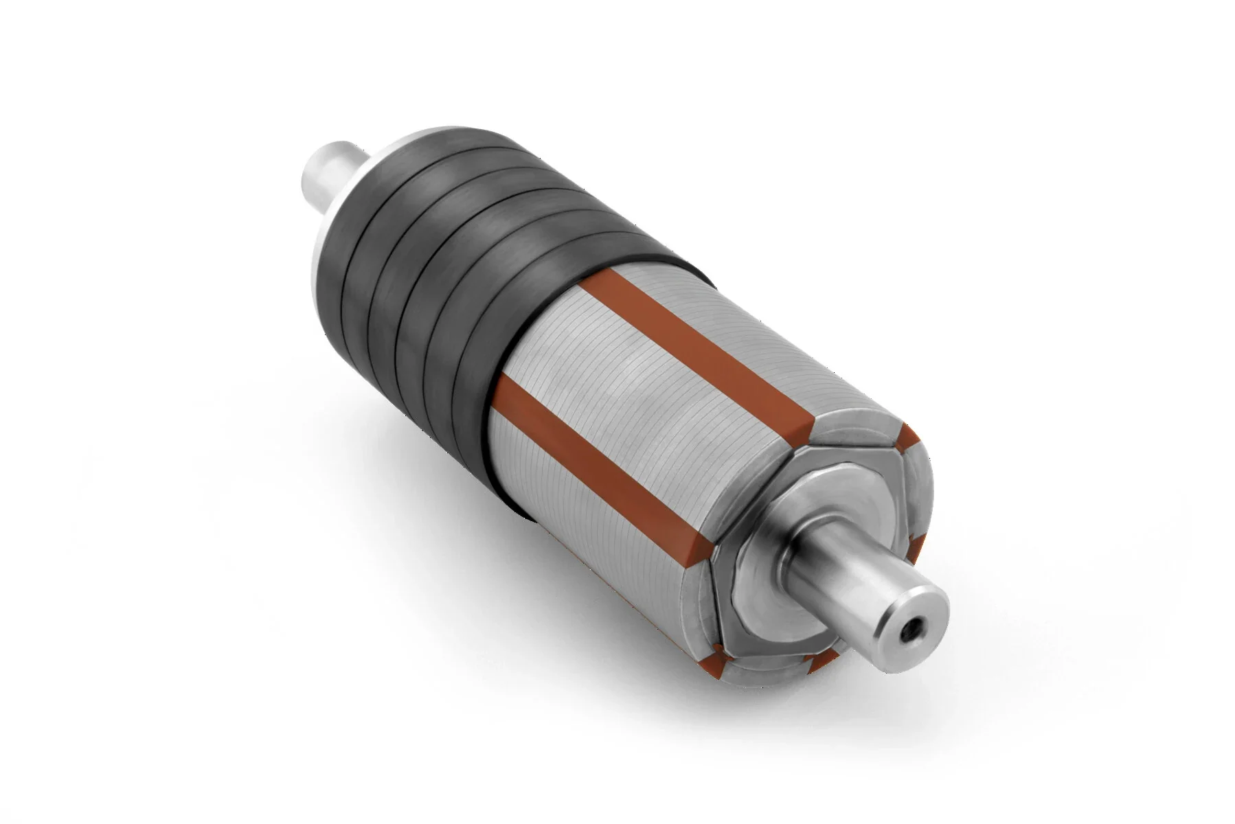
Integrated magnetic and mechanical motor subassembly.
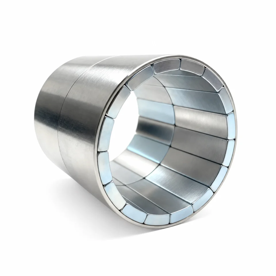
Segmented construction for constrained assembly space.
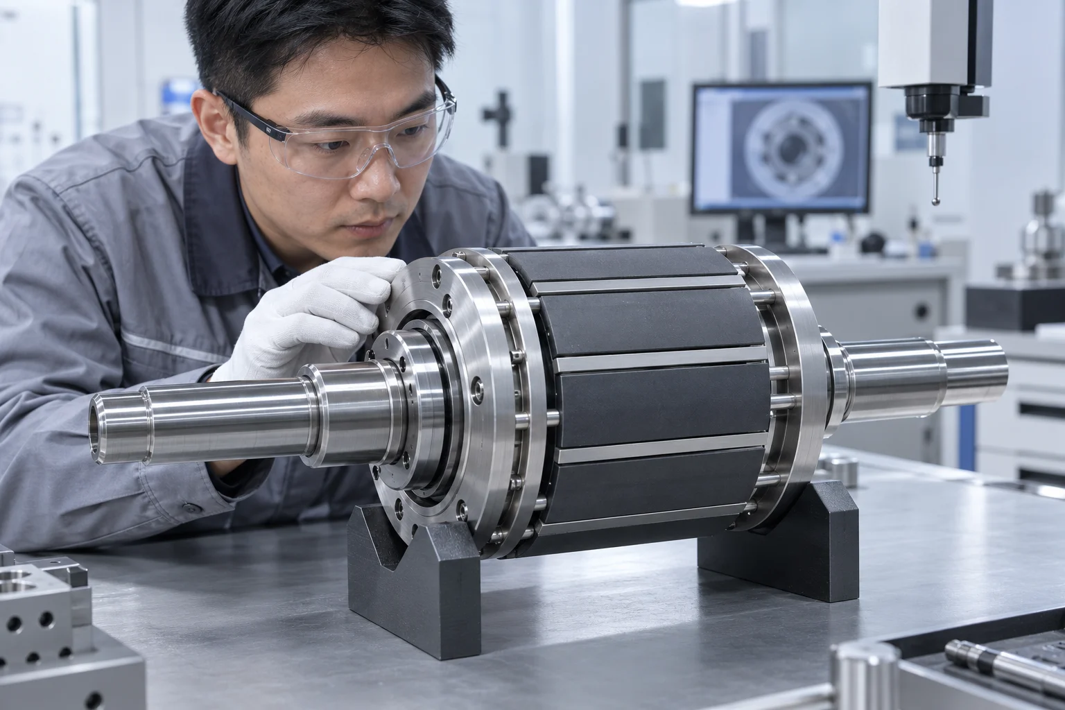
The shaft datums, magnet locations and retention system define the inspection object. Review sleeve / bond interfaces with operating speed, temperature and assembly clearance.
Agree runout, balance planes and field-mapping conditions before release. Acceptance records must refer to the drawing revision and completed rotor configuration.
Review assembly quality controls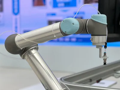
Magnets, shafts and stacks received or produced; dimensions verified
Bonding or overmolding under controlled process parameters
Magnetized in fixture; pole pattern and flux verified
Two-plane dynamic balancing to specified grade
Final flux signature, runout and dimensional release
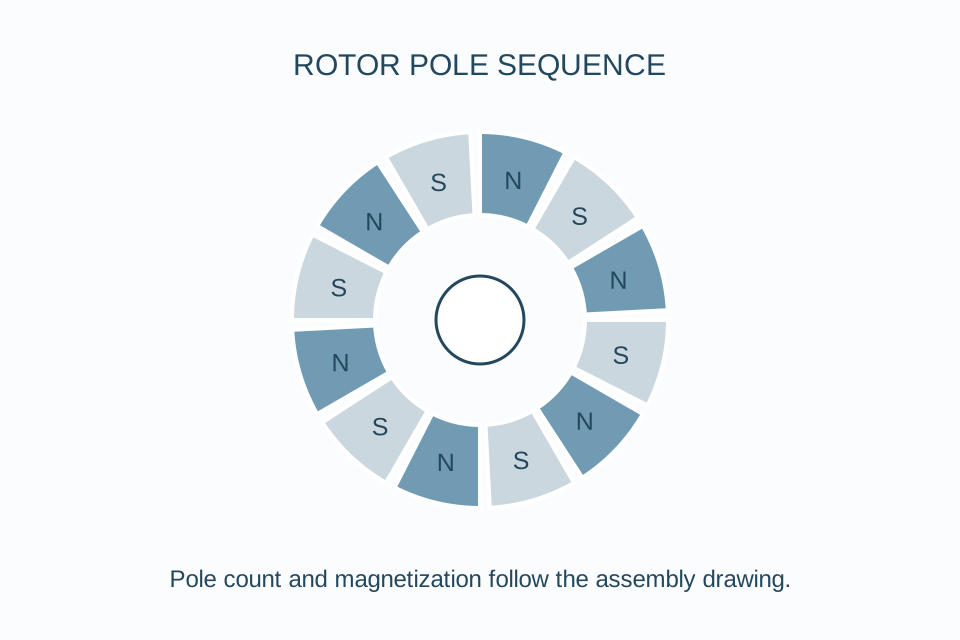
Review field shape and pole pattern against the agreed magnetic targets.
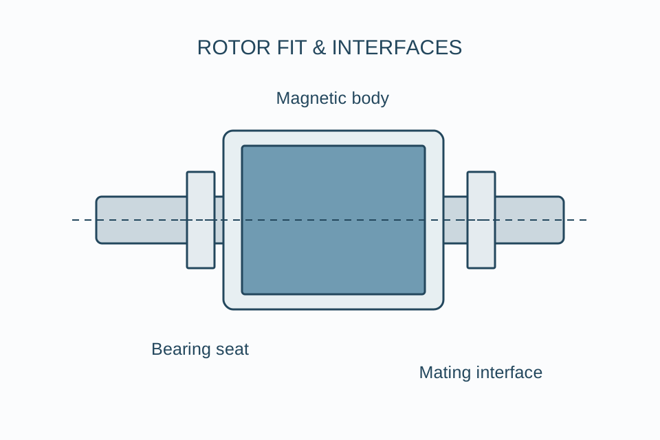
Relate measured features to the datums and interfaces on your assembly drawing.
Radial, diametric, multi-pole or skewed — verified per pole on production assemblies.
High-temp epoxy or overmolding; shear strength tested on production samples.
Two-plane dynamic balancing to G2.5 (ISO 21940) standard, G1.0 on request.
Ground magnet OD and journals — 0.01 mm TIR runout reference, measured from the agreed datum axis.
Pole-resolved field or flux signature using the agreed fixture; measurement method and lot records defined in the inspection plan.
Flux data, balance records and dimensional reports per the agreed inspection plan.
Inspection scope, acceptance criteria and the required records are agreed for each rotor design.
Every component, from the magnet grade to the balancing plane, is engineered and verified as one system.
NdFeB / SmCo / bonded — grade matched to temperature and performance spec
Stainless, carbon steel or Alloy 42 — machined and ground to ±0.005 mm
Silicon steel 0.2–0.5 mm — die-cast or interlocked
High-temp epoxy, anaerobic or insert-molding — shear-tested
Stainless or carbon-fiber containment for high surface speeds
Magnetization, flux signature, runout and dynamic balance
 SELECTION GUIDEApplication selection notesExplore applications and requirements
Magnet handling, bonding, magnetizing, and balancing are specialized processes — outsource them to us and focus on your motor winding and final assembly.
| Application | Typical Spec | Why This Material |
|---|---|---|
| BLDC Motor Rotors | N42SH arc segments on lamination stack | Efficient, compact motor cores |
| Pump Rotor Assemblies | Overmolded magnets on stainless shaft | Hermetically sealable wet rotor designs |
| Compressor Rotors | SmCo segments for high-temp | Refrigeration and HVAC compressors |
| Fan Rotors | Injection-molded ring magnets | High-volume cooling fan production |
| Automotive EPS Rotors | N48UH with high-retention adhesive | Steering systems needing extreme reliability |
Typical capabilities — send your drawing for a specific quote.
| Parameter | Capability | Notes |
|---|---|---|
| Magnet materials | NdFeB N35–N54, SmCo 1:5/2:17, bonded NdFeB | Grade matched to your temp and performance spec |
| Shaft materials | Stainless 304/316/416, carbon steel, Alloy 42 | Machined and ground to ±0.005mm |
| Lamination stacks | Silicon steel 0.2–0.5mm | Die-cast or interlocked stacks |
| Bonding | High-temp epoxy (180°C), anaerobic, or overmolding | Shear-tested per lot |
| Magnetization | Radial, diametric, multi-pole, skewed | Verified per pole on 100% of production |
| Balancing | G2.5 standard, G1.0 available | Two-plane dynamic per ISO 21940 |
| Runout | 0.01mm TIR on magnet OD | Ground and 100% inspected |
Magnets on shaft / lamination stack — balanced and ready to install.
One-sided, uniform-field arrays engineered to your air-gap target.
Insert-molded magnets for sealed rotors and harsh environments.
Magnetic couplings and custom assemblies built to your drawing.
FAI / PPAP documentation is scoped to project requirements. Dimensional, magnetic and balancing records follow the agreed inspection plan.
View the five assembly quality controlsSend us your drawings — we'll flag these before quoting:
Provide any of these — the more complete, the faster and more accurate the quote:
Identify the approved drawing revision, sample reference and acceptance records for a repeat-order handover.
Review program qualificationProcess reference images are separated from the product gallery. They illustrate equipment and handling topics; they do not establish ownership of a facility, a customer delivery, or project-specific inspection results.
Rotor programs combine automated magnet insertion, fixture-controlled assembly, final magnetization, dynamic balancing and protected tray packing.
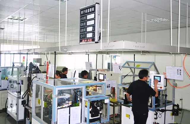
Enclosed equipment places magnet segments into rotor or stator fixtures.

Organized workstations maintain pole orientation, bonding and traceability.
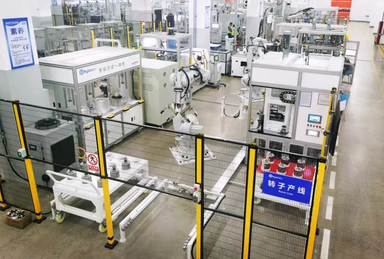
Enclosed cells integrate magnet loading, magnetization and controlled rotor assembly for serial production.
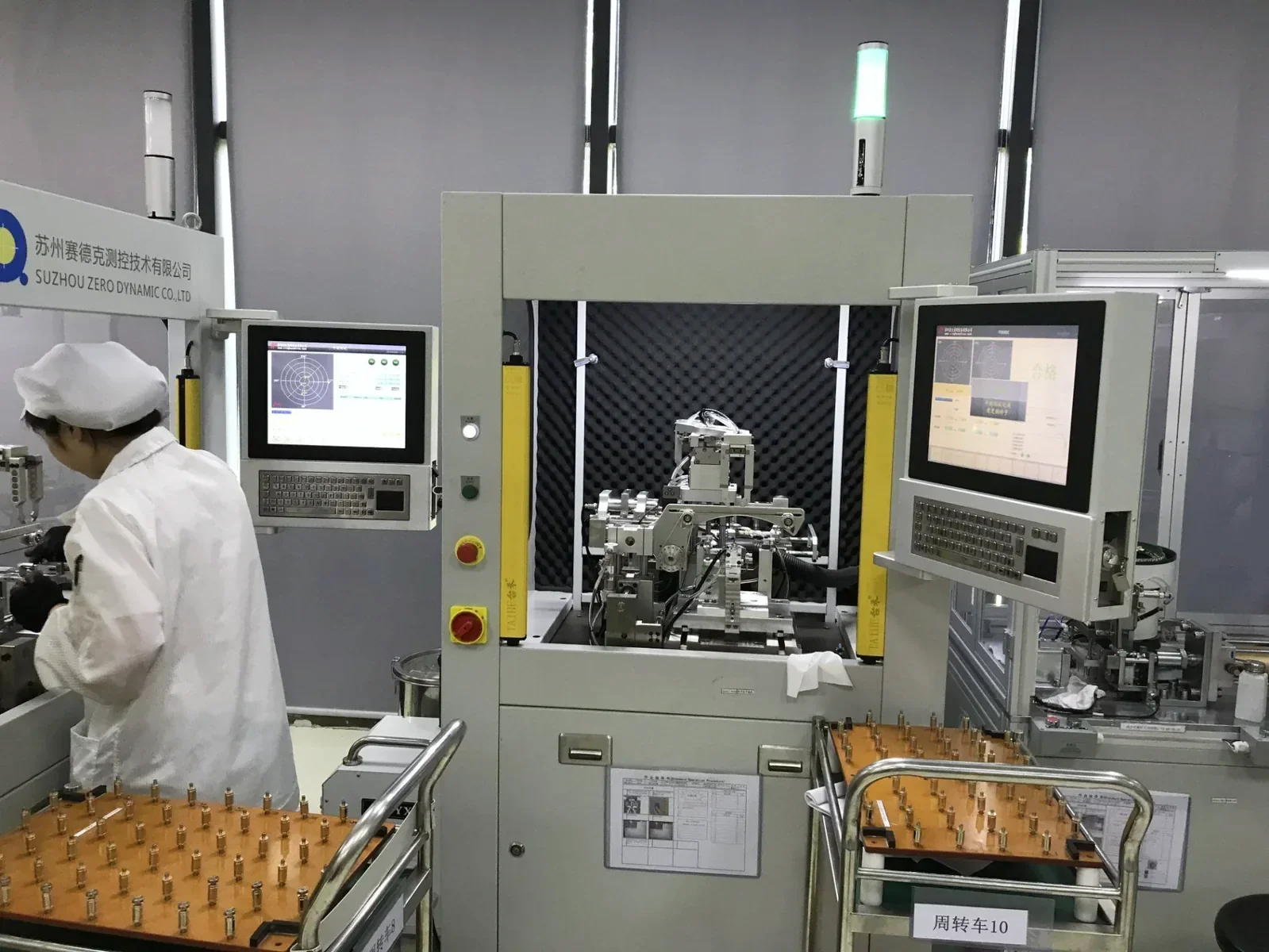
Dual-plane balancing equipment checks residual unbalance before release.
An illustrative design review might consider an N38UH segmented rotor, a retention sleeve and dynamic balancing. Grade selection alone does not validate 180 °C continuous operation; the magnetic circuit, thermal duty and retention system require project-specific validation. This is not a documented customer delivery.
Yes — we source or manufacture lamination stacks per your drawing, or accept customer-supplied stacks for assembly. Die-cast aluminum and interlocked stacks are both available.
The inspection plan defines pole-resolved Hall-probe mapping, a suitable search-coil fixture or functional back-EMF testing as appropriate. A Helmholtz coil measures magnetic moment and alone does not resolve every pole of a multipole rotor. Agree fixture geometry, temperature, limits and shipment records before production.
We balance to G1.0 for high-speed applications like turbocharger and aerospace components. Achievable residual unbalance depends on rotor mass, service speed, geometry, correction planes and fixture repeatability; review these together for tighter requirements.
Prototypes: 2–4 weeks including magnet production. Volume production: 4–8 weeks depending on annual volume and tooling requirements. We hold safety stock for repeating programs.
Send it to our team for engineering review and quotation — assembly drawings and BOMs welcome.