
For Logistics
Packing, destination and delivery terms — discuss the shipment requirements for your order.
Coordinate deliveryInner and outer magnet rings transmit torque across a containment barrier without a rotating shaft seal at that barrier. Containment integrity, static joints and contamination control require project-specific validation for pumps and mixers handling hazardous, ultra-pure or sterile fluids.
MOQ, lead time, packaging and commercial terms — go straight to a quotation.
Request a QuoteGrades, drawings, process data and design support for your DFM review.
Magnet Design GuideCertificates, inspection planning, traceability and PPAP / FAI support per project.
Certificates & DocumentationPacking, destination and delivery terms — discuss the shipment requirements for your order.
Coordinate deliveryProduct forms, uses and selection considerations. Final specifications are agreed for each project.
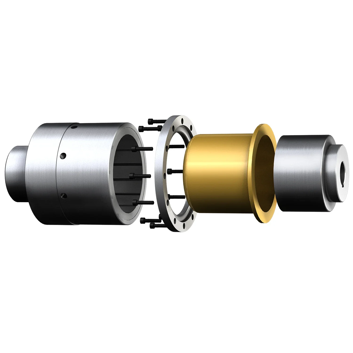
Rotating members and isolation barrier reviewed together.
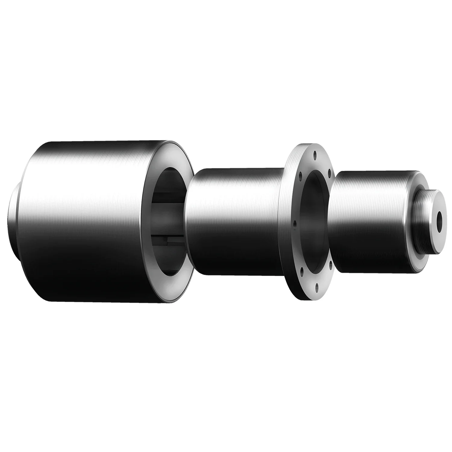
Mounting, containment and fluid requirements defined together.
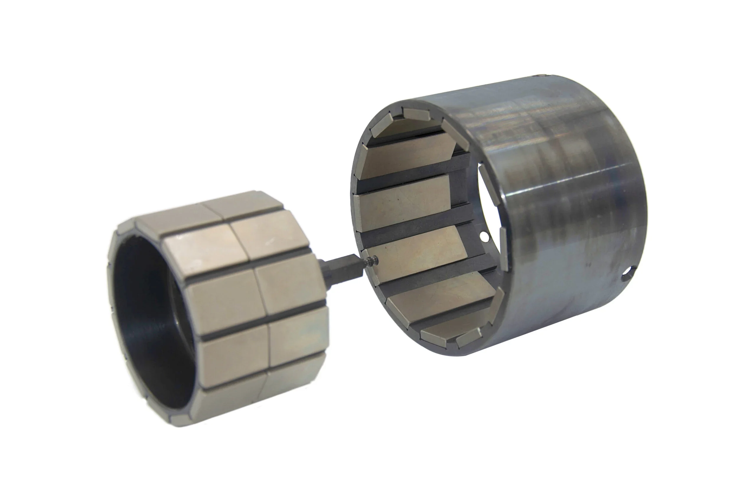
Magnet arrangement and clearance inform torque review.
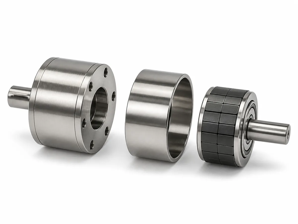
A complete inner-member, outer-member and barrier system.
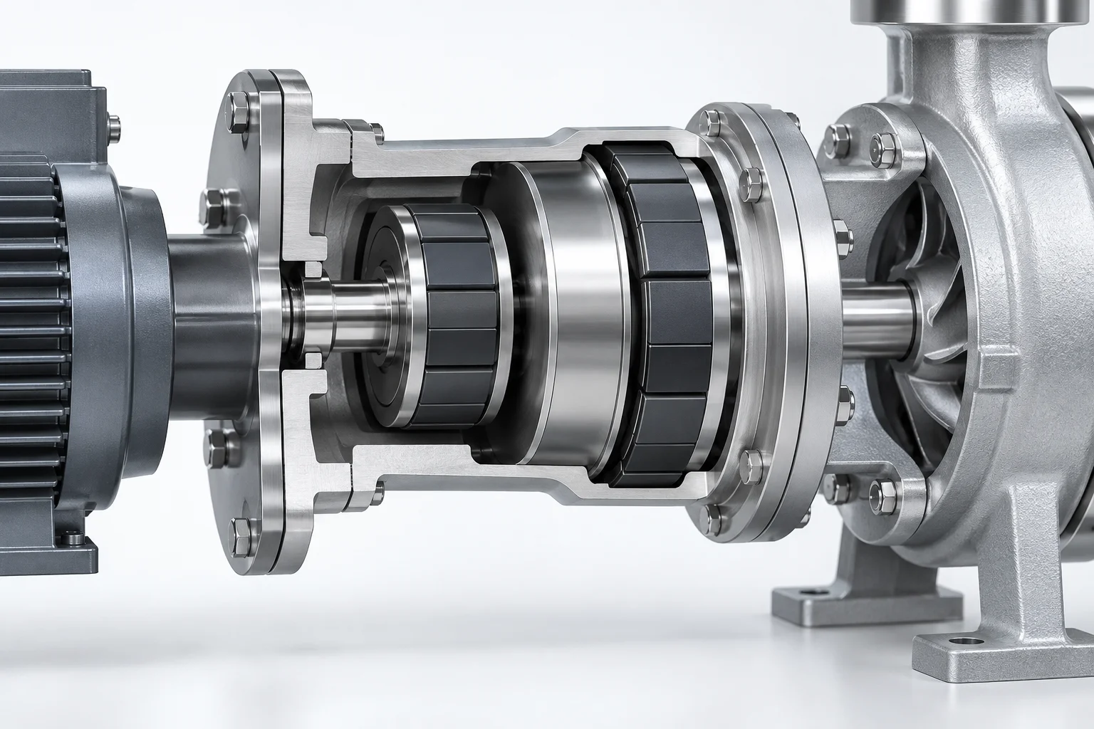
Inner and outer magnetic members transmit torque across a containment barrier. Available gap, alignment and barrier material affect the coupling design and thermal review.
A sealless drive removes the rotating shaft-seal path; it does not certify system-wide zero leakage. Specify pressure, medium, static joints and leak-test acceptance separately.
Review coupling design parametersEvery shaft seal is a leak path — a maintenance item and a contamination risk. A containment-can magnetic drive removes the rotating shaft seal at the barrier. Static seals and other system interfaces still require integrity review.
| Application | Typical Spec | Why This Material |
|---|---|---|
| Chemical Process Pumps | SmCo in Hastelloy can | Pumping acids, solvents, and toxics |
| Pharma Mixers | SmCo in 316L stainless can | Sterile-process use requires hygienic design and validation |
| Semiconductor Fluid Handling | SmCo in PEEK can | Media compatibility and extractables require validation |
| Refrigeration Compressors | NdFeB in thin steel can | Hermetic compressor drive |
| Laboratory Reactors | SmCo in glass-lined can | Sealed reaction vessels |
Provide rated and peak torque, speed, fluid, pressure and temperature. The published ranges below are design references, not a tested catalogue rating; confirm the complete operating envelope for the selected assembly.
| Parameter | Typical Range | Notes |
|---|---|---|
| Torque | 0.1–500 Nm | Custom designs; sintered NdFeB or SmCo |
| Speed | Up to 10,000 RPM | Higher with special balancing |
| Temperature | -40°C to 350°C | Select grade, retention and barrier for the full thermal duty |
| Containment can | 316L, Hastelloy C, PEEK, glass | Material matched to fluid |
| Gap | 1–5mm typical | Smaller gap = more torque per volume |
| Decoupling torque | 1.3–2× rated torque | Protects against overload |
Two coupling technologies for different requirements:
The containment can must satisfy pressure, chemical, thermal and magnetic requirements together:
Size a torque coupling with torque, speed and containment requirements—not a magnetic-wheel pull-force value.
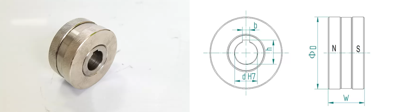

Source: archived TY Magnets dimensional references. The drawings illustrate the retained source notation; they do not establish Empire supply approval or pull-force test results.
Dimensions are in mm, except thread designations such as M4. Pull force is in N and weight in kg. These magnetic-wheel references are separate from torque-coupling selection; N is not torque in N·m. The archived supplier table uses TY-W/TY-R identifiers; the historical EM-W/EM-R references below require an approved part-number mapping, drawing revision and pull-test conditions before selection.
Discuss a custom magnetic assembly
| Part Number | D (mm) | d (mm) | W (mm) | b (mm) | h (mm) | Pull Force | Weight |
|---|---|---|---|---|---|---|---|
| EM-W-25 | 25 | 8 | 16 | 3 | 8.6 | 55 N | 0.054 kg |
| EM-W-32 | 32 | 10 | 18 | 4 | 11.1 | 80 N | 0.100 kg |
| EM-W-40 | 40 | 12 | 20 | 4 | 13.1 | 120 N | 0.200 kg |
| EM-W-50 | 50 | 16 | 25 | 5 | 17.3 | 200 N | 0.350 kg |
| EM-W-63 | 63 | 20 | 32 | 6 | 21.7 | 330 N | 0.700 kg |
| EM-W-80 | 80 | 25 | 40 | 8 | 26.7 | 630 N | 1.450 kg |
| EM-W-100 | 100 | 30 | 50 | 8 | 31.7 | 900 N | 2.800 kg |
| EM-W-125 | 125 | 40 | 62 | 12 | 42.1 | 1520 N | 5.350 kg |
| Part Number | R (mm) | L (mm) | W (mm) | H (mm) | W1 (mm) | H1 (mm) | R1 (mm) | M | W2 (mm) | L1 (mm) | Pull (0mm) | Pull (3mm) | Pull (5mm) |
|---|---|---|---|---|---|---|---|---|---|---|---|---|---|
| EM-R-5040 | 50 | 40 | 76 | 36.5 | 42 | 12.5 | 26 | M4 | 64 | 18 | 490 N | 230 N | 150 N |
| EM-R-5060 | 50 | 60 | 76 | 36.5 | 42 | 12.5 | 26 | M4 | 64 | 38 | 820 N | 400 N | 260 N |
| EM-R-8040 | 80 | 40 | 115 | 51 | 76 | 20 | 49 | M5 | 102 | 18 | 730 N | 400 N | 300 N |
| EM-R-8060 | 80 | 60 | 115 | 51 | 76 | 20 | 49 | M5 | 102 | 38 | 1250 N | 730 N | 540 N |
| EM-R-10040 | 100 | 40 | 152 | 62 | 100 | 26 | 64 | M5 | 138 | 18 | 850 N | 480 N | 340 N |
| EM-R-10060 | 100 | 60 | 152 | 62 | 100 | 26 | 64 | M5 | 138 | 38 | 1500 N | 900 N | 650 N |
| EM-R-12040 | 120 | 40 | 172 | 70 | 120 | 30 | 80 | M5 | 158 | 18 | 1000 N | 600 N | 420 N |
| EM-R-12060 | 120 | 60 | 172 | 70 | 120 | 30 | 80 | M5 | 158 | 38 | 1750 N | 1100 N | 800 N |
| EM-R-15040 | 150 | 40 | 200 | 77 | 142 | 31 | 104 | M6 | 186 | 18 | 1200 N | 750 N | 560 N |
| EM-R-15060 | 150 | 60 | 200 | 77 | 142 | 31 | 104 | M6 | 186 | 38 | 2100 N | 1350 N | 1050 N |
Process reference images are separated from the product gallery. They illustrate equipment and handling topics; they do not establish ownership of a facility, a customer delivery, or project-specific inspection results.
Magnetic couplings require matched inner and outer subassemblies, controlled magnet integration, torque testing and non-destructive inspection.
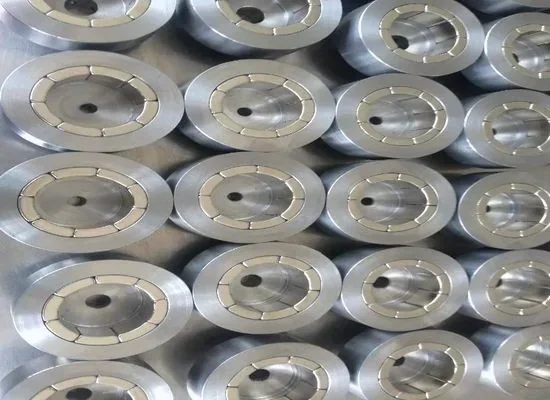
Ring-shaped metal components are staged in trays. This reference image does not show magnet polarity or a matched inner / outer magnetic set.
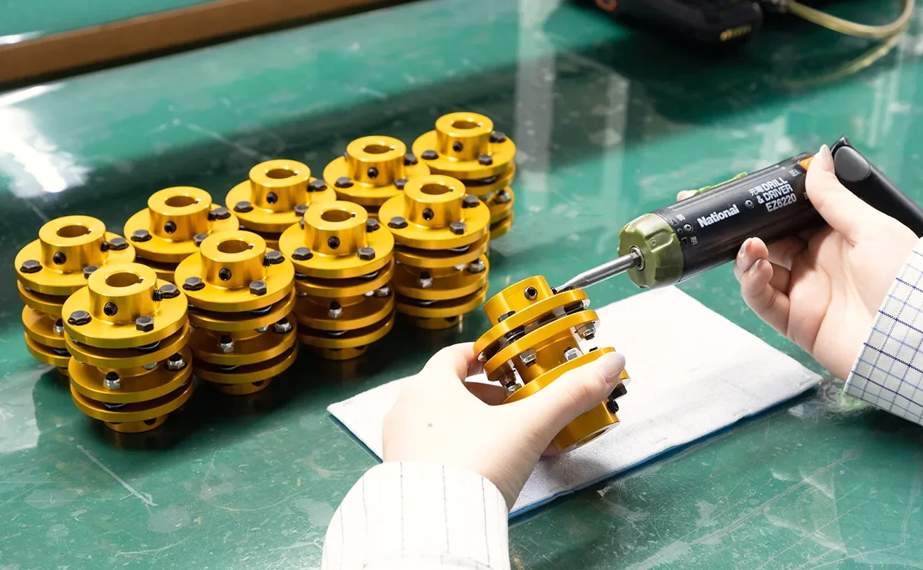
Torque-controlled tools support small-coupling assembly and alignment.
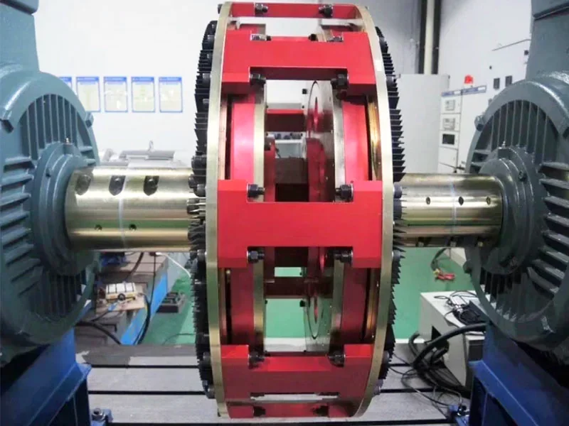
Drive and driven sections are aligned for assembly-level evaluation.
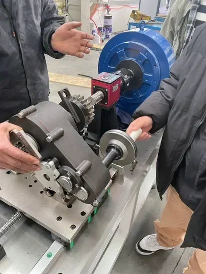
Instrumented benches measure torque transfer and rotational response.
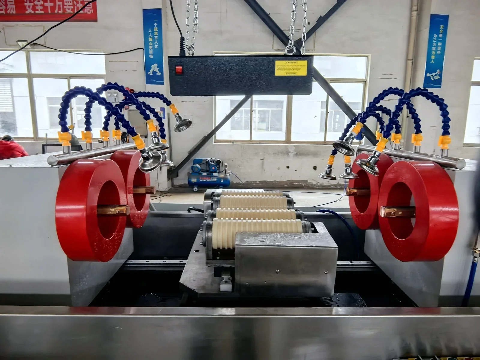
Fluorescent magnetic-particle inspection detects surface or near-surface defects.
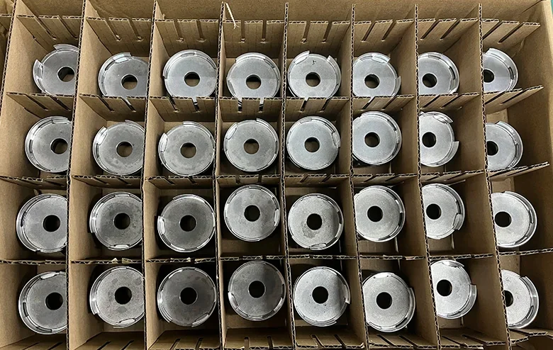
Dividers separate metal components. Restraints and moisture protection are agreed for the finished coupling and shipment.
Above pull-out torque, a synchronous coupling can lose synchronism and the driven side may stall or rotate irregularly. Continued slip can generate heat, so define detection, shutdown and restart conditions. The published 1.3–2× ratio is a design reference; transient loads and the validated torque envelope determine the actual setting.
Efficiency depends on speed, load, gap, containment material and losses in the complete drive. The 99% headline is a published reference, not a test result for your design. Agree the torque/power measurement boundary and temperature-rise limits; conductive cans require an eddy-current-loss review.
Yes — send us your pump's torque requirement, shaft sizes, fluid, pressure, and temperature. We'll design a coupling retrofit with the decoupling torque, can material, and mounting interface specific to your application.
The magnetic members transfer torque without contact. Bearings, containment, fasteners, retention and the driven equipment still need inspection under the equipment maintenance plan; contactless torque transfer alone does not establish a maintenance-free pump.
Agree pull-out torque, operating duty and temperature conditions for design validation. Request the applicable torque-versus-angle or temperature data for the selected configuration; no project-specific curve is published on this page.
Pressure and leak testing of containment cans to your spec — for pumps, mixers and hermetic drives.
Rotating assemblies balanced to your G-grade requirement; concentricity of hubs verified for smooth high-speed operation.
Include medium, temperature, speed and available installation space when requesting a coupling review.
Share operating conditionsSend it to our team — we'll review the design and quote it as a validated, ready-to-install assembly.