
Verify the Operating Point
Review the magnetic circuit and temperature together rather than selecting a grade from a temperature number alone.
Read selection guidanceSpecify the magnetic function, operating conditions, geometry, coating and assembly requirements before selecting a material or grade.
Most design mistakes come from picking a material first. Instead, define what the magnet must do:
With the requirements defined, the material choice usually narrows itself:
| If you need… | Choose |
|---|---|
| Maximum force in minimum space | NdFeB |
| Stability above 150–200°C or in corrosive media | SmCo |
| Lowest cost, large sizes, corrosion immunity | Ferrite |
| High temperature with gentle handling | AlNiCo |
| Bendable, cuttable, print-ready sheets | Flexible |
Full property comparison: Material Specifications.
Review temperature together with the magnetic operating point.
NdFeB grades carry a temperature suffix: standard N grades to ~80°C, M to 100°C, H to 120°C, SH to 150°C, UH to 180°C, EH to 200°C, TH to 220°C. These are conventional grade references, not guaranteed part limits. Irreversible loss can occur below them if the magnetic circuit or opposing field is unfavorable.
Thin magnets or magnetic circuits with a low permeance coefficient can have less demagnetization margin. Review the load line and demagnetization curve at the actual magnet temperature.
Agree the design margin using the actual magnetic circuit, demagnetization curves, continuous and peak temperatures, and opposing fields. A fixed percentage or temperature offset is not a universal selection rule; validate the operating point with engineering before release.
Review the magnetic circuit and temperature together rather than selecting a grade from a temperature number alone.
Read selection guidanceNdFeB requires protection; other materials often don't. Match the coating to the environment:
| Coating | Thickness | Best For |
|---|---|---|
| Ni-Cu-Ni | 15–20 µm | General purpose, 48–72h salt spray |
| Epoxy | 15–25 µm | Outdoor, marine — 240h+ salt spray |
| Zinc | 8–12 µm | Cost-sensitive, dry environments |
| Parylene-C | 5–20 µm | Medical, thin and pinhole-free |
| Phosphate | ~2 µm | Vacuum, clean, short-term storage |
SmCo, ferrite, and AlNiCo generally need no coating.
Sintering affects final dimensions. Define the functional faces and required tolerances so machining or grinding can be planned where needed:
The magnet is part of a system — design the system.
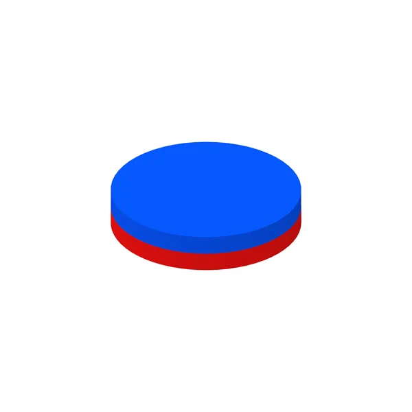
Define the field and magnetization direction.
Specify the finished geometry before manufacture.
Agree supply condition and shipment protection.
Protect surfaces and inspect contact features.
 SELECTION GUIDEMagnetization, assembly and handling guidanceExplore applications and requirements
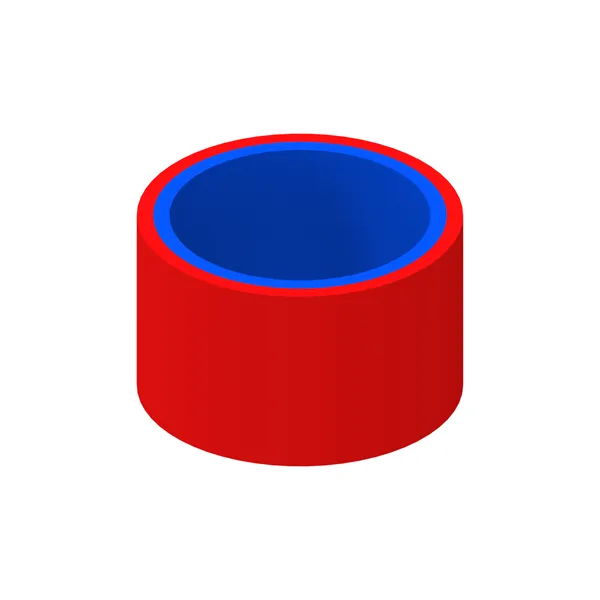
Define magnetization direction, pole pattern and accuracy in the drawing. Material orientation and magnetizing-fixture requirements constrain the available patterns; agree the magnetization and assembly sequence before production.
Sintered NdFeB and SmCo are brittle; mounting features require a manufacturability review. Grinding or specialist cutting may be needed. Threads and press-fit interfaces are usually provided by a housing or backplate; bonded-material machining depends on the formulation.
Charged magnets simplify your line but complicate transport (IATA rules). We ship either way, with proper packaging and documentation. Tell us your assembly process and we recommend the best option.
Define contact points, separation and packaging for the intended coating and assembly sequence.
Review coating guidanceSend your drawing or concept. Our engineers check the magnetic circuit, temperature margin, and manufacturability, then recommend the most cost-effective spec.